Balustrades · System selection
Top-mounted or face-mounted balustrades? Start with the slab edge
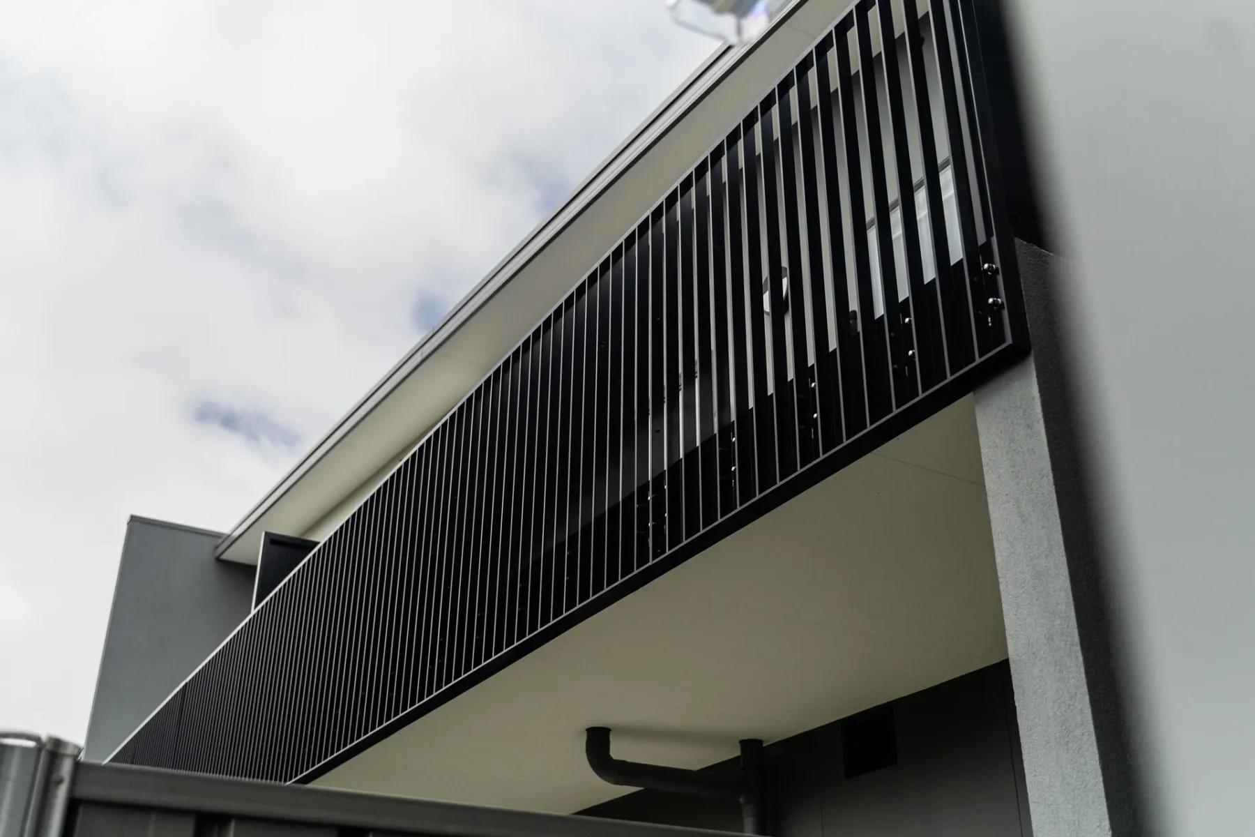
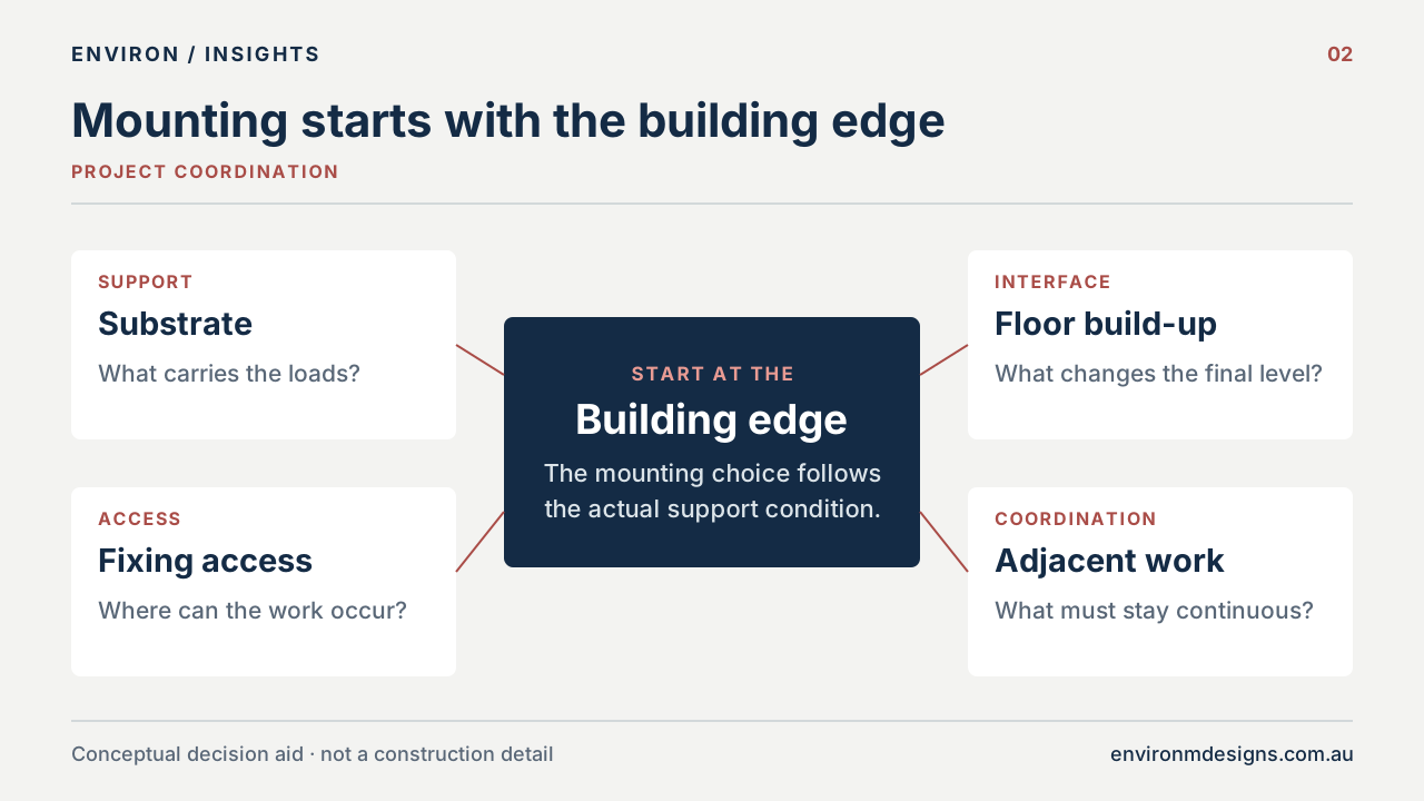
The slab edge often makes the first balustrade decision. It determines where a fixing can be reviewed, how the floor finish meets the panel and what the installer can reach. Begin with that condition and the system comparison becomes more useful than choosing a rail profile from an elevation alone.
Read the edge in section, not only in elevation
An elevation shows the architectural rhythm: rail height, infill spacing, panel divisions and returns. A section explains how the balustrade meets the building. Include both in the enquiry so the intended appearance can be considered alongside the structure and finished floor.
Identify the structural slab, steel or engineered framing that is intended to support the system. Then show the layers between that structure and the walking surface. A fixing drawn against a thin finish line is ambiguous if the screed, paving or pedestal-supported deck is still being developed.
Access belongs on the same section. Can the installer work from above, reach the outside face or access both sides before the façade is closed? This is useful design information even when the exact anchor arrangement is still for the project engineer to resolve.
Compare the mounting approach before the individual code
Environ’s named systems group several approaches within the broader top, base, face and wall mounting conditions. The starting point below is a selection conversation, not an assessment of structural capacity.
A project may use more than one approach. Balcony runs, stair transitions and wall-to-wall openings can present different support conditions, even when they share a rail profile and finish. Record those changes as distinct locations rather than forcing the whole building into one assumed detail.
Scroll table horizontally
| Approach | What to establish | Relevant Environ references |
|---|---|---|
| Top-mounted | Available structural fixing surface, floor build-up, access from above and relationship to the edge. | Top-mounted with spacers; T-section; slab-cover arrangement |
| Discrete base plates | Plate positions, support beneath each fixing zone and coordination with the finished surface. | Base-plate mounted |
| Face-mounted | Vertical edge geometry, access outside the edge and the intended fixing band or below-slab extension. | Face-mounted with angle, bottom angle or plate |
| Between structural supports | Location and suitability of end supports, clear opening and panel-to-support connections. | Wall-mounted |
Top-mounted does not mean one standard base detail
Environ’s Top-mounted with spacers system uses a continuous base fixing plate and spacers. Its T-section system uses a continuous T-shaped fixing assembly and is a reference for tile-pod setups or restricted slab-edge access. The Top-mounted for slabs system includes an aluminium slab-cover plate around its fixing arrangement.
These are materially different edge conditions. Show whether a cover is intended to conceal the slab edge, whether a clear zone is needed beneath the panel and where the floor finish terminates. A comparison is more precise when the architectural intent is stated alongside the structural information.
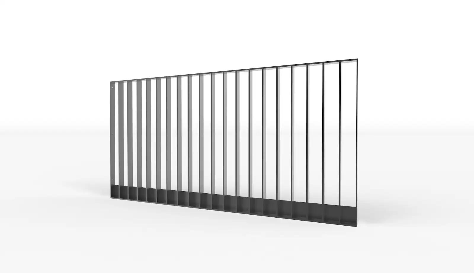
The Base-plate mounted system uses discrete plates rather than a continuous bottom fixing plate. The position of those supports is part of the panel and fixing design. It should not be inferred from a photograph or repeated at an assumed spacing from another project.
Face and wall mounting need their own access discussion
Face-mounted systems can form a defined band along a slab edge or extend the balustrade members below it. Environ’s range includes angle, bottom-angle and plate arrangements. The desired line of the assembly should be shown clearly, together with the actual edge and any adjacent façade components.
Before choosing that approach, establish when the edge will be accessible and who will coordinate it with the surrounding construction. A visually open edge early in the programme may become difficult to reach after cladding, screens or neighbouring work is installed. Raising that question early allows the site team to assess the sequence.
Wall-mounted arrangements work between structural supports. Show the end conditions and identify their construction. An opening between finished wall faces does not, by itself, explain the support available behind them. The intended connection needs to be reviewed against the supporting structure.
A useful brief describes the condition that is unresolved
Consider an illustrative apartment balcony with pedestal-supported paving. The architect wants a continuous slim top rail. The builder can reach the slab from above, while outside access is limited. The useful enquiry records those facts and includes a section through the finished paving and structure.
It would be premature to turn that information into a fixed plate size or anchor schedule. It is enough to ask Environ to review a top-mounted arrangement, including the T-section reference, against the available structural and architectural information. The project team can then resolve the detailed fixing and surrounding interfaces.
Now consider an exposed vertical slab edge where the architectural intent is a continuous fascia line. That is a different brief, even if the rail and infill are the same. Keeping those locations separate makes both the quotation and drawing review clearer.
Bring the rail and infill back into the complete assembly
Once the mounting condition is understood, compare the slim and thick rail references and the available blade, twin-blade, slat, square-batten or rod infills. Panel divisions, corners and wall junctions still need to be coordinated across the elevation.
Include any associated privacy screen or change in barrier function. Adding a taller or denser element is a change to the proposed assembly, not simply a different finish. It needs to return to the project review with the relevant dimensions and requirements.
The balustrade requirements guide explains why dimensions and evidence must remain attached to the actual building condition. For an initial mounting discussion, send the plans and edge sections that are available now. Mark missing information rather than guessing a detail to complete the enquiry.
Reference desk
Sources and further reading
Primary guidance and resources for the decisions discussed in this article. Check the edition and requirements that apply to your project.